
These images were made at W5SXD with various receivers.
Most of the images were recorded with my spectrum analyser program called SPAN.
Some were made by Spectran, the great program by I2PHD, Alberto DiBene, and IK2CZL, Vittorio.
The moon reflection image was made with AF9Y's old DOS program, FFTDSP.
The signal source for some of the airplane reflections was the 216.980000 MHz CW transmitter
at Lake Kickapoo, Texas, about 100 miles west of Dallas.
I had to see the antenna for myself and drove out to the site several years ago and took these pictures.
The antenna consists of 2560 dipoles as seen above in a 2 mile long array half of which is shown below.
The center of the antenna is at 33°33'22.28"N by 98°45'47.49"W and it can be seen on Google Earth.
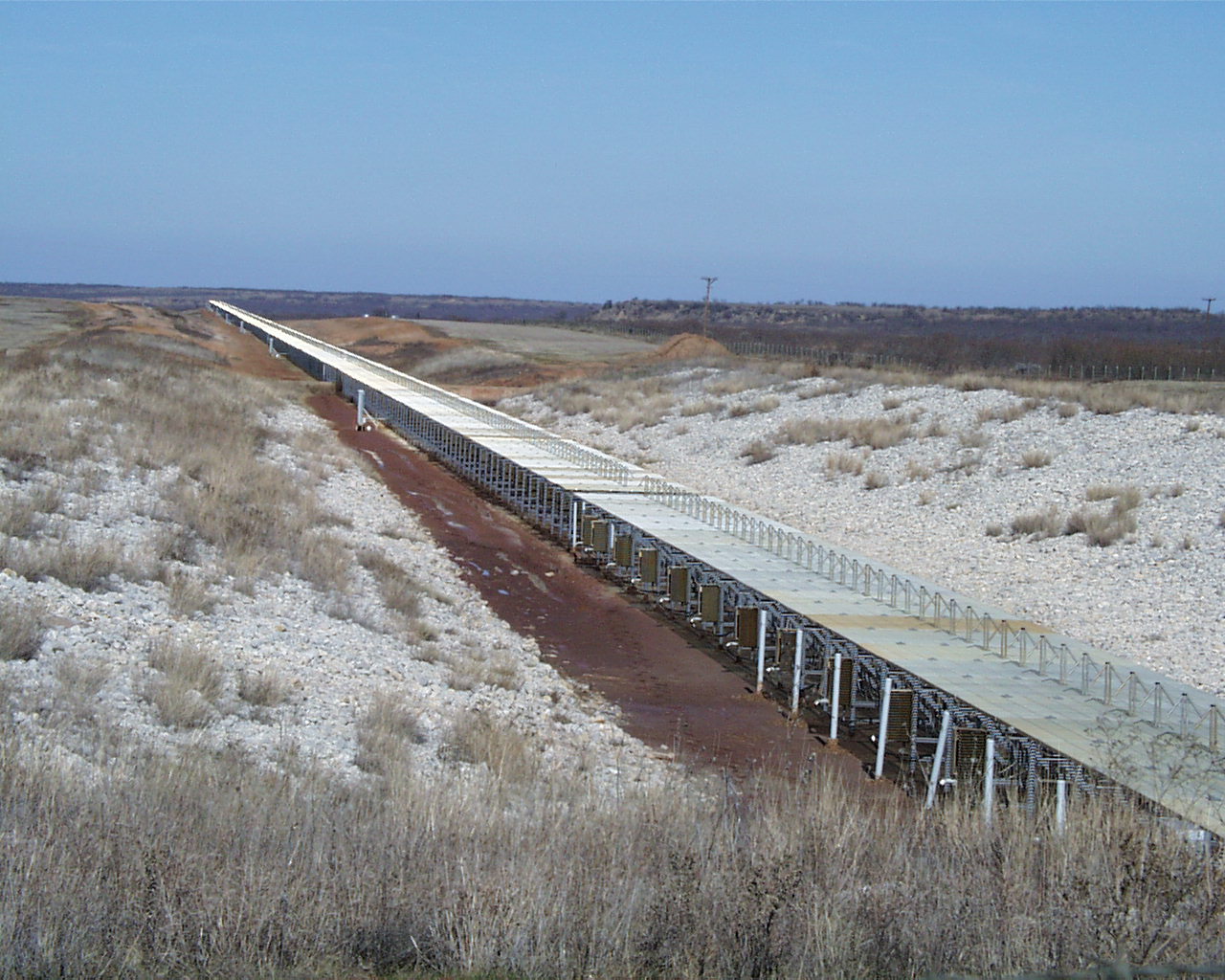
This is the north half. The transmitter sends out a constant carrier 24 hours a day. The ERP at 216.98 MHz is over 6 billion watts.
You can find out more by searching for NAVSPASUR on Google or going to
http://www.k4gfg.us/navspasur/index.html
One of the first images that I made was of the Lunar reflection of the 216.98 MHz signal.
I calculated when the Moon and my location would have a common window thru the beam
of the antenna and what the Doppler shift would be.
I obtained the following on the first attempt using a five element 222 MHz yagi pointed at the rising moon.
The following images were made with the waterfall display of my own spectrum analysis program, SPAN.
The receiver was an icr8500 tuned to USB 216.979000 to produce a 1000 Hz center frequency.
The straight line at 1000 Hz is the main carrier. The S shaped curves are the airplane reflections. There is a lot of air traffic to the west of Dallas.
The receiver was in Mineral Wells, Texas, about 70 miles southwest of the transmitter.
The next picture is of a series of satellite passes from Orbcomm satellites that have a fixed carrier output at about 400 MHz.
The receiver was controlled by my satellite tracking software so that the Doppler shift was corrected. Each satelllite should
produce a straight line. These traces show that both the satellite element sets and the tracking software were
working very well. The time of closest approach for each pass is indicated along with the maximum elevation.
The following plot is from an Lusat-Oscar 19 pass. Lo19 transmits a Morse code telemetry
message on about 437.125 MHz. The width of the traces in these plots is caused by the 10 Hz tuning steps
of the icr8500and also the cw keying modulation.
The little pcr-1000 radio with it's 1 Hz steps make a much nicer plot once it's frequency inaccuracies are accounted for.
The next image is a plot from one of the Goes satellites timing channels on around 468 MHz. The exact frequency
less 1000 Hz was dialed into the 8500 on USB.
That radio has an excellent timebase being less than one vfo step off of the Goes frequency.
Since the satellite was in geosynchronous orbit, the Doppler shift was very small.
This recording was made on 2011 May 24 on six meters with a 5 element yagi and a flex5000. The beacon, K5AB, is about 150 miles West
of W5SXD and transmits very close to 50.060000. The straight line is the ground wave signal which is audible here almost 24 hours per day
at about -120 dBm, barely moving the meter. The sidebands out to about +/- 8 Hz are caused by the keying of the carrier.
The right hand ticks are one Hz apart and the red ticks are one minute apart. 600 Hz represents 50.060000.
This image also shows Doppler shifted airplane reflections, the slanted traces, that are sometimes louder than the main signal.
The above example shows the occurrence of positive Doppler slope. Since the source is in a fixed location and the
reflector is moving relative to both the source and listener and the two Doppler shifts add together we can sometimes see the positive slope.
This is again the K5AB beacon on 50.060000 monitored at W5SXD 150 miles to the East.
When the k5ab 50.06000 beacon gets loud, interesting sidebands can be seen. They are caused by the cw keying modulation. Here
the signal was about s4 at my place in el29ep. The noise floor was about -120 dBm.